2021
August 05: ESP and solar panel Part 2; the results2020
December 26: ESP and solar panel Part 1; the setup August 22: ESP-8266 power issue with ME6206 regulator2019
October 18: How to use alarm syscall in Ruby2018
December 20: Decode Oregon Scientific sensors with RaspberryPi and Arduino2016
October 19: How I recovered a dead hard drive with a freezer September 28: Drawing a ground plane in Kicad June 27: Quick Ruby On Rail memo2015
December 18: Signal handling and Ruby December 14: EventMachine is good but... September 18: My custom ortholinear keyboard February 08: Quick Sinatra boilerplate2014
September 16: Wifi access point on a Raspberry Pi March 24: Linphone and G729 on Opensuse2013
November 11: Ext4 rescue tips November 05: Why this blog is'nt running Wordpress ?ESP and solar panel Part 1; the setup
- December 26, 2020
The goal of this serie of articles is to see how we can power 24/7 a small ESP-8266 setup, for example a remote wheather station, with a solar panel and a Li-ion cell.
As the chip run on 3.3V and a Li-ion cell between 2.8V and 4.2V, a 6V solar panel seems to be the best fit. A 12V panel would induce more losses during power convertion.
What size of solar panel do we need
As Andrea Spiess explained in his video #142, the math is not so complicated :
- An ESP needs an average of 80mA (with spikes at 170mA but we can ignore that). At 3.3V, that's around 270mW (3.3V * 80mA).
- According to Solargis studies, the horizontal irradiance is around 950 kWh/m2 per year where I live.
- As there is 8760h in a year, the maximum available theoretical power is 108 W/m2 (950 kWh / 8760 h)
- With a solar efficiency at 15% plus some losses at 10% on the way, that's a maximum available realistic power of 14W/m2. So 1.4mW/cm2
- Wich gives us a minimum size of 193cm2 (0.33W / 14W/m2). So, short answer, take the biggest panel you can fit.
Which controller to choose
From the multiple technologies and vendors available on the market, two controlers stands out for such small systems with 6V solar panel and one Li-Ion cell : TP4056 and CN3791.
The CN3791 from Consonnance seems to be the best choice on paper. It's a 1 cell Li-ion switching charger desiged to run from solar panel with MPPT functionnality.
The TP4056 is not a solar controler, just a linear li-ion charger that runs on 5V USB power. But according to various sources on the Internet, it seems to work well with 6V solar panel as their MPP voltage is around 5V.
Some other controllers or regulators could be used but are not optimized to charge Li-ion batteries and could damage the cell.
Power path
When running a system from battery, it's usually very bad to power the device directly from the battery while it's charging at the same time. The current drawn by the device will interfere with the charge controller. This one will not be able to detect when the battery is fully charged and may over-charge it. On the other side, if the battery is completely discharged (like below 2.5v) the charger will enter into the trickle mode with a very low charging current that will no be enough to power the device. It will not work and the battery will never charge.
This would be the case for a RasberryPi, for example, that can take up to 2A at 5V. In this case, a "power path" is needed. It's a kind of automatic switch to select the power source for the device and use the battery only when there is no other sources.
Such "auto-switches" are easy to make with a P-channer MOSFET and a Schottky diode. Here is an example of typical application :
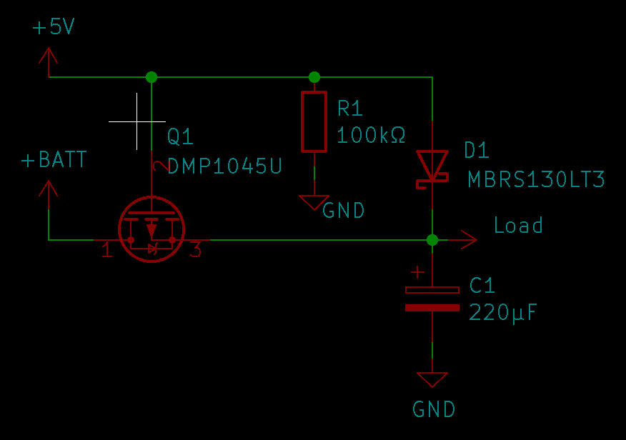
For an ESP866, the current drawn is in average around 70mA. That is low enough and will not change much the charging current (around 1A on most TP4056 board). Worst case scenario the battery protection will kick-in to prevent overcharging. With an added voltage controller to switch off the load (like the ESP and a FP6298) when the battery goes below 3.3V, it will protect against over-discharge and prevent the charger to to on into trickle mode.
So a power path is not really necessary if the load is smaller than ~100mA, but definitely needed if bigger.
Voltage detector
According to the datasheet the ESP minimum voltage is 3.0V. Below that it should crash, but some tests showed that it was still working at 2.5V. Anyway the risk of a crash caused by undervoltage is high. So we need a voltage detector to shutdown the EPS when the voltage is getting below 3.0V
If we add the dropout voltage of the ME6206 regulator, which has been mesured around 150mV at this load, we need a voltage detector at 3.15V. As the ESP seem to still work until 2.5V, a detector around 3V should do the job. That will shut off the ESP at around 2.8V and increase the usable battery voltage range.
I did some tests with a KA75330, but there where not succesful. Probably a defective component. So I went with a TPS3839G33 from a more reliable vendor and got the expected behavior. The ESP shutdown properly at 2.8V and starts again to work when the voltage rise.
Diode or not diode
In this kind of setup, we usally see two diodes being used : One schottky diode in serie to block reverse current at night, and a zener in parallel to clamp the open-circuit voltage.
The blocking diode will prevent the battery to dischage thought the panel when there is no sun. A simple diode should be ok instead of the schottky, the voltage loss will be higher, bringing the 6V from the panel down to around 5V. Not a big deal but this might change the MPPT setting or lower the efficiency when the sun is low.
When the battery is fully charged and the controller stop pulling power, the panel will be in open-circuit. In some case the resulting high voltage can burn the controller. These 6v solar panel usually have an open-circuit voltage around 7.5v, below the maximum input votage of the TP4056. It's safe to connect them directly. Otherwise a zener diode should be put in parrallel of the panel to keep open-circuit voltage below the maximum input voltage of the controller. The effective open-circuit was mesured at 7.6v on my panel in full sun but drop quickly after a couple of minutes to 7V, as the panel is heating up. So this diode is not needed in my case.
Let's run some tests
To compare both of these controlers, we will do a full test over multiple days and compare their power efficiency in full sun, in the shade and at night. The "at night" test for a solar system might seems ridiculous but is indeed very important to make sure the controler is not discharging the battery when there is no sun.
The testing setup is basically composed of :
- The controler to test
- A 3.3V voltage regulator ME6206
- A 3.0V voltage detector KA75330Z
- An ESP8266
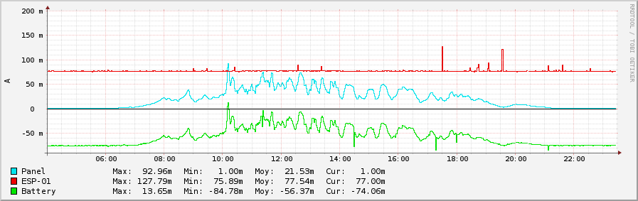
- 3 INA219 to measure the power at the battery, the panel and the ESP.
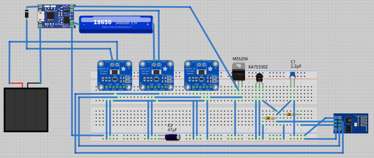
The sketch on the ESP simply fetches the values from the INA sensors and send them to a graphing system based on RRDTool. I did not use deep sleep on the ESP to keep the load constant. With the 3 INA chips, it draw ~80mA, that's 250mW. With deep sleep, the average consumption would be way lower than the one mesured (as the chip wakes up to do the mesurement) and wouldn't be accurate. This is ony for the test of course. In real life, deep sleep will increase the battery time.
First results
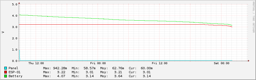
Interestingly, when there is no direct sunlight, the solar panel still produce a very litte power, around 150mW. Not enough to charge the battery, not enough to fully power the load, but it still use to reduce the current drawn from the battery which only need to provide the remaining 100mW needed. That mean a power path setup that select the power source from the battery OR the solar panel wouldn't be efficient in this usecase, as the power is coming from the battery AND the solar panel.
The LDO voltage reguator I choose, ME6206, does'nt seems to be very good. The ouput is a bit low with only 3.22V instead of 3.3v. During the first tests, the ESP stopped working when the battery reach 3.7v which shouldn't be the case with its 200mV dropout voltage. This issue is caused by the regular current spikes of the ESP (see previous post for more details). More testing is required with others LDO regulators, like HT7333, MIC5209-3.3YS-TR or TPS73633DBVT. But that's a story for another day.
A voltage detectory to turn off the ESP properly when the battery is low is definetely mandatory, and might require some tunning.
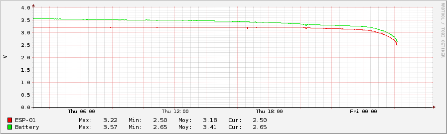
With no voltage detector, the runtime is around 41.5 hours at 75mA. That's a capacity of 3150mAh. Not bad for a no-name 3400mAh battery, taken in account the ESP stops around 2.7V, while the full battery capacity is reach at 2.4V. With a voltage detector at 3V, the runtime is 41h. Thats a very small reduction and offer more stability.