2021
August 05: ESP and solar panel Part 2; the results2020
December 26: ESP and solar panel Part 1; the setup August 22: ESP-8266 power issue with ME6206 regulator2019
October 18: How to use alarm syscall in Ruby2018
December 20: Decode Oregon Scientific sensors with RaspberryPi and Arduino2016
October 19: How I recovered a dead hard drive with a freezer September 28: Drawing a ground plane in Kicad June 27: Quick Ruby On Rail memo2015
December 18: Signal handling and Ruby December 14: EventMachine is good but... September 18: My custom ortholinear keyboard February 08: Quick Sinatra boilerplate2014
September 16: Wifi access point on a Raspberry Pi March 24: Linphone and G729 on Opensuse2013
November 11: Ext4 rescue tips November 05: Why this blog is'nt running Wordpress ?Decode Oregon Scientific sensors with RaspberryPi and Arduino
- December 20, 2018
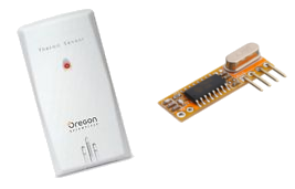
Once upon a time, I wanted to improve my home automation system with some temperature and humidity information. For that purpose, Oregon Scientific sensors are very good, quite cheap and uses RF 433Mhz to communicate.
The protocol is also well documented : http://wmrx00.sourceforge.net/Arduino/OregonScientific-RF-Protocols.pdf
So I bought one sensor, a bunch of cheap 433Mhz receiver and started digging around.
The RaspberryPi solution
I quickly found Paul amazing work on Disk91 :
- https://www.disk91.com/2013/technology/hardware/oregon-scientific-sensors-with-raspberry-pi/.
- https://www.disk91.com/2015/technology/systems/rf433-raspberry-pi-gpio-kernel-driver-for-interrupt-management/
With few adaptation to run it on my setup, I got some working results.
I did lots of tests with both versions. The first version uses userland irq and the second uses a kernel module to manage interruptions. Both are working but have different sensitivity to noise.
This setup worked for a while but the range is quite short and the process use up lots of CPU cycle, way too much for the small tasks at hands. I believe this high CPU usage is caused by the noise around the receiver generating a lot of useless interruptions on the input pin. The use of the kernel module to manage these interruptions improved the CPU usage but the overall range got shorter by a few meters.
Random luck
Globaly, thess receivers are very sensitive to noise and a very minor change of configuration can have a major impact of the quality of the reception.
For example, when I moved slightly the antenna, the kernel module version stopped receiving data while the userland version was still working good (around 5m range). When I put it back in the same place both version worked again but with a very bad reception range (below 1m).
Sometime having somebody passing by the door will change a lot the quality of the signal, it's really difficult to identify the good setup as there is so many hidden parameters.
Radio communications can be tricky...
The RasberryPi itself, the USB power supply, the Wifi router and all the cables must generate tons of interference, probably high frequency ones. I unfortunately dont have a scope to check the quality of the received signal or even the noise on the 5V line of the RaspberryPi.
Strangely, I've got better range result while powering the receiver with 3.3v instead of 5v despite the datasheet of the receiver saying the range should be better with a higher voltage. That difference suggest me that the 5V line of the RaspberryPi must be very noisy.
Filtering the power supply
To improve the reception range, I tried to tackle the noise issue by adding some filters to clean the 5V power line.
I first put some capacitors here and there, like 10nF, 220nF and 220uF. I didn't see any major improvement but that can't hurt. I would need a scope to properly identify which kind of noise is there and put the good capacitors.
The 5V on the RasberryPi is taken from a USB power adaptor. So I down went this path and look for a way to filter USB power line.
I found the official recommended way to properly filter USB power supply in this document from FDTI, page 8:
It uses a buch of capacitors in parallel and a ferrite bead in serie. Andy Brown did a really good job here in testing this filter : http://andybrown.me.uk/2015/07/24/usb-filtering/
That looked promising but after bulting all that, I still didn't see major improvements...
Next time I will try to shield the RaspberryPi and the receiver, that may help a bit.
A better antenna
I also tried different kind of antennas to improve the reception range. When there is radio involved, you can't go anywhere if you dont have a good antenna.
There is lots of documents on the web related to 433Mhz antennas, but three kinds are commonly seen : 1/4 wave, helical and coil loaded wire.
Here is a picture of the ones I succedded to build :
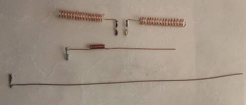
For more instructions on how to build these, there is good reading here :
- https://www.instructables.com/id/433-MHz-Coil-loaded-antenna/
- https://github.com/OpenHR20/OpenHR20/wiki/2.1)--433-MHz-and-868-MHz--Antenna-Design-Examples
As you can see on the following picture of the internals of an Oregon sensors, it uses a double coil antenna.
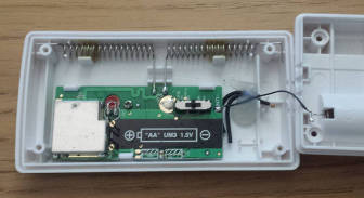
So I tried the same one as well but the results were not very convincing. The 1/4 wave straight wire seems to do the best job but there is so many influencing factors, it's very difficult to have a good idea of the performance of an antenna. It's more likely to be largely influenced by the quality of the receiver and obscure randomness.
The quality of the signal can also vary a lot over time without any environment changes.
The Arduino version
After spending a long time running tests and optimization with the RapsberryPi setup, I was still unable to get a range better than a few meters, not enough for my needs. So I gave up and tried with an Arduino, which does a better job for realtime interruption processing.
I used the Oregon library provided with the Arduino IDE, very simple to use and work very well. I got a way better range than with the RaspberryPi... if the Arduino is far away ! If I put it beside the Pi, it's not working anymore. Damn noise !
You can find more details about this setup here : https://github.com/nagius/heatman/tree/master/misc/oregon
Weirdly the Arduino UNO gave me a better range (couple of meters more) than the Arduino Nano, despite the use of the same microcontroller, same power supply, same cables, same antenna, same spot on my desk...
Conclusion
These Oregon Sensors are very good but it very difficult to get a good reception and reliable data flow. It's working but not always. My temperature graph are full of holes. If I have the choice, next time I will pull some cables and use a wired communication, something like long distance Serial or one-wire.